Controlling large underfloor heating systems – °CALEONbox for advanced users
Reading time: 8 min
The control of underfloor heating systems consists of the zoning as well as a functional integration with the rest of the heating system, such as the heating flow and the energy source.
Most multi-zone controls for surface heating systems are designed for up to 8 zones, like the °CALEONbox. This is sufficient for many residential units and smaller single-family homes.
Wherever the number of zones exceeds 8, several wiring centres must be linked together and should work seamlessly to provide optimum control of the entire system. These applications are referred to here as large systems and include
- large houses and villas with >8 rooms
- multi-storey single-family houses with separate manifolds per floor
- multi-family houses with their own multi-zone control per residential unit
- commercial buildings such as offices or hotels
- public buildings such as schools or hospitals
Using several °CALEONboxes in a single-family house
To realise installations with more than 8 zones, wiring centres must be modularly expandable. They should not only work as separate silos, but control the system as a whole and provide a consistent user experience (UX) as if from a single source.
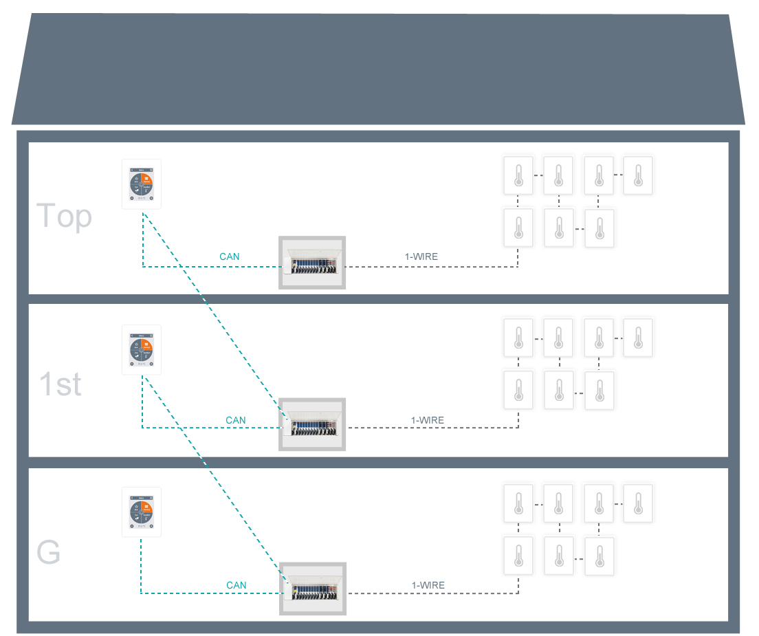
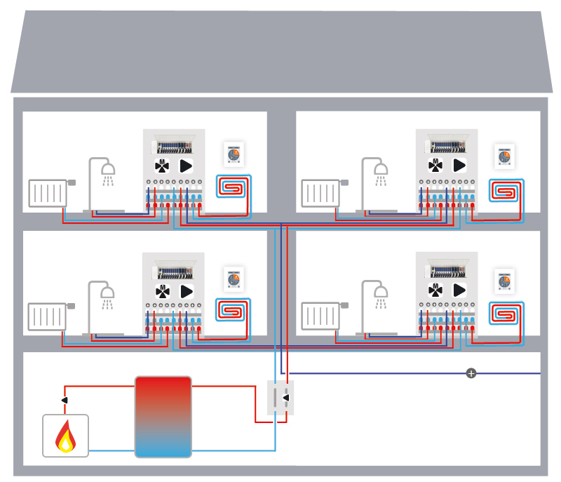
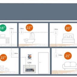
If the system is a single residential unit, such as in larger detached houses, several °CALEONboxes can easily be combined to form a consistent system.
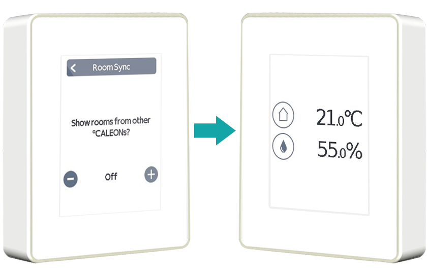
All data is automatically shared between the installed components via CAN bus. Thanks to the multi-room feature, the user can access all rooms from all connected °CALEONs as well as the °CALEON app – regardless of the physical assignations between the devices.
Up to 3 °CALEONboxes can thus be combined into a seamless private system (as of November 2020, software version 31370).
Info box: Field buses of the °CALEONbox
The °CALEONbox uses two bus technologies, CAN and 1-Wire, with different advantages that optimally meet various aspects of the system requirements.
CAN bus
Suitable for the fast transmission of larger data volumes and over longer lines. Thus, more data-intensive information such as operating times and statuses can be transmitted up to remote parameterisation and software updates.
The CAN bus is therefore used for communication between the °CALEONbox and °CALEON Room Controllers as well as on many other SOREL controllers such as the HCC series.
The CAN bus is a 2-wire bus (CAN high: white. CAN low: brown), which must be installed in series from device to device. There must be a 120 Ohm terminating resistor at each end of the line, which is usually pre-mounted at the SOREL factory.
1-wire bus
A digital bus, which thus enables almost any number of sensors to be connected to only 1 terminal port. The number of sensors is therefore not limited by the clamp terminals of the controller hardware.
This is exactly what the 1-wire bus is used for with the °CALEONbox: to connect temperature and humidity sensors such as the room sensors, floor sensors, flow and return sensors or outdoor sensors to the wiring centre. Compared to the CAN bus, however, the 1-wire bus is optimised for small data volumes and medium cable lengths.
Attention: despite the name “1-wire”, in reality 3 wires should be used! The misleading term originates from the automotive industry, where the car body forms the ground and the data line is combined with the power supply. This shortens the cable length considerably, but in the automotive sector these are limited anyway due to space constraints.
A 3-wire cable layout with supply voltage, data line and GND allows more sensors to be connected to the °CALEONbox and longer cable lengths to be achieved. With 1-wire, the cable routing should also be in line from device to device, with short spur lines being permitted.
For clear and simple assignment when using several 1-wire sensors on one °CALEONbox, each 1-wire device is labelled with a unique ID. It is recommended that this ID is noted during installation and noted with the corresponding zone.
°CALEONbox Networks in multifamily houses and commercial buildings
In apartment buildings or hotels, on the other hand, only your own housing unit should be visible, but not the private information of your neighbours. It is still advantageous to connect the systems across flats, for example to share an outdoor sensor or to link the individual systems to a central heating system.
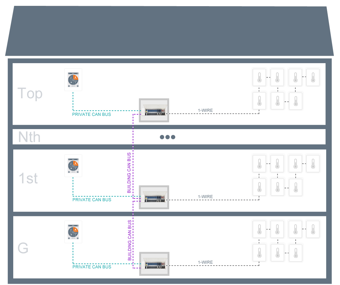
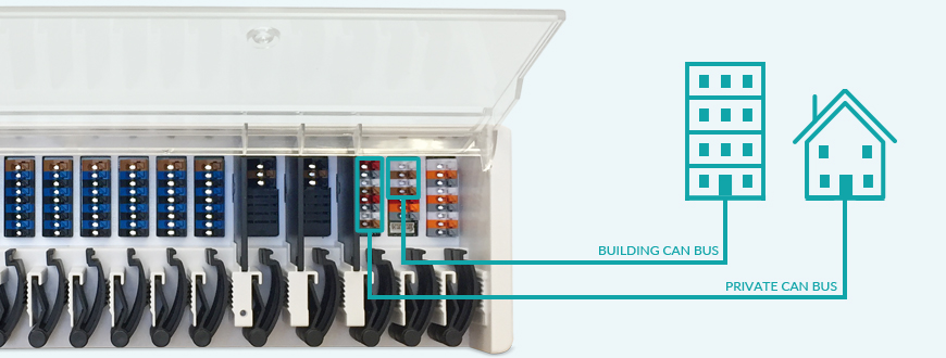
Equipped with two separate CAN bus slots, the °CALEONbox enables both: to control large systems holistically and protect privacy at the same time.
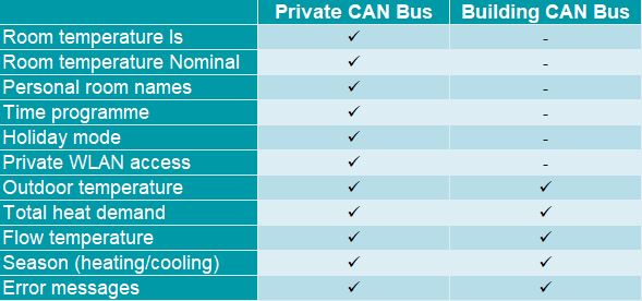
The private CAN bus is therefore used within a residential unit, as in the above example of the three-storey detached house. In the private CAN bus, all target and actual temperatures, room icons and names as well as system-wide settings such as the activation of the holiday mode are thus freely shared.
In contrast, the building CAN bus only shares information that is useful for controlling the overall system across residential units, such as the outside temperature, system-wide fault messages or the heating/cooling season. The building CAN bus is also interesting for decentralised fresh water systems, see also “Electronic heat interface units”.
Since less data is transferred in the building CAN bus, up to 50 °CALEONboxes can currently be integrated into the same building CAN network. As every °CALEONbox controls up to 8 zones, this results in a theoretical system size of up to 400 rooms – or more on a project or OEM basis.
Overview which CAN network shares which data. In single-family homes, the distinction is not necessary and all information can simply be communicated via the private CAN bus.
Control of the flow temperature in apartment buildings
The flow temperature in apartment buildings is usually controlled in two ways:
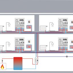
a) Each residential unit has its own heating circuit control. This variant is usually used with higher system temperatures – e.g. with partial heat transfer via radiators or integration of decentralised fresh water technology – or due to corresponding subsidies.
Ideally, the heating circuit control is weather-compensated and influenced by room temperature. This combination achieves the highest temperature stability.
In the °CALEONbox system, residents can set their desired temperature room by room. The weighting of the room temperature compared to the weather-compensation can be adjusted by the technician in the expert menu of the °CALEON Room Controller.
The mixer is controlled via configurable additional outputs of the °CALEONbox and the outside temperature is shared system-wide via the building CAN bus.
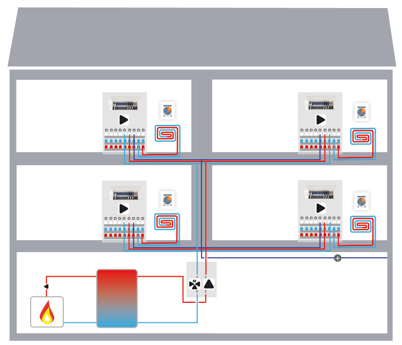
b) In many cases, the control of the central flow temperature is isolated from the multi-zone controls in the flats and is determined, for example, by the controller of the heat source. As the central control system therefore does not know the actual demand, it is often set to an over-supply and thus compromises energy efficiency.
°CALEONbox systems, on the other hand, can be optionally supplemented with an HCC heating controller. As these communicate with each other via the building CAN bus, the flow temperature can be adapted to the cumulative heat demand from all residential units according to the situation.
Within each residential unit, multi-zone control runs as usual via the private CAN bus.
Access management in large systems
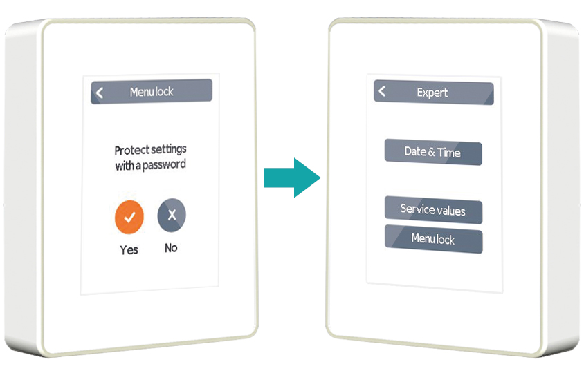
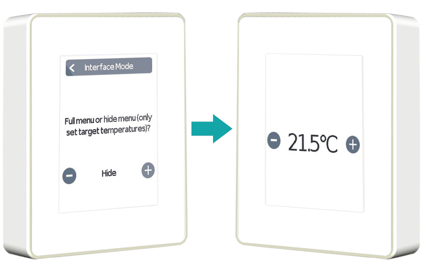
Particularly in commercial or public surface heating systems, different user groups require different levels of authorisation. For example, office staff should not be able to make system settings, hotel guests should be restricted to their own room and residents of a retirement home should be given the simplest possible operating options.
°CALEON Room Controllers offer three levels for restricting the user interface:
Integration into building management systems
In the course of the rise of connectivity in HVAC systems, surface heating systems are also increasingly linked to building management systems (BMS). However, these are still the exception and also use diverse protocols. The occasional use of bus converters, e.g. from CAN to Modbus or BACnet, can fulfil this requirement where necessary without making the standard devices more expensive.
To the extent that BMS integration is becoming more widespread and a standard protocol such as Modbus emerges, a direct interface on the °CALEONbox can be implemented on an OEM basis to query operating states or set temperatures.
Opportunities of remote servicing for installers and manufacturers
There is often a higher service requirement for large-scale systems, as they are technically more complex on the one hand and, on the other, operational reliability is particularly important for legal or economic reasons.
By upgrading the freely available °CALEON App, which provides the end customer with basic functions such as the adjustment of target room temperatures or time programs, to °CALEON App Pro, the expert gains access to the entire °CALEON menu.
Many service cases can thus be solved much more quickly and cost-effectively from afar – particularly relevant in regions with long distances and high labour costs.
Ongoing system monitoring and optimisation also enable a higher service level, or as part of a maintenance contract, even additional sources of income for the trade and system manufacturers.
Since the °CALEON App Pro can even run the integrated commissioning wizard of a °CALEONbox system, manufacturers can also offer their customers a novel service: a guided remote setup. The installer is merely the executing body, while a specialist from the manufacturer takes over the system configuration via app. As an option, the installer can watch and learn live in front of the device on the construction site.
Clever system providers can also add checklists to the installation in order to ensure correct cabling and configuration. He could use this as part of an all-round carefree package as a sales strategy to reduce the usage barriers to their systems, raise the success rate of the installations and strengthen the personal bond through direct contact with the plumber.
Checklist for the installation of °CALEONbox large systems
✓ CAN bus wired in line from device to device, not e.g. star-shaped
✓ 1-wire bus wired in line from device to device. Short spur lines possible.
✓ Shielded, twisted pair cable used. At least 4 wires, 6 wires recommended.
✓ Maximum cable length respected: CAN bus cable max. 200m | 1-wire cable max. 100m
✓ Power supply of maximum 8 °CALEON Room Controllers via the °CALEONbox. If necessary, install a suitable external power supply unit (24VDC).
✓ All devices within a residential unit connected via private CAN bus (terminal block L), devices across residential units connected via building CAN bus (terminal block M)
[Disclaimer: The information provided here is intended to provide additional guidance on the correct installation of °CALEONbox systems according to the status at the time of publication. The official technical specifications can be found in the respective operating instructions]


